|
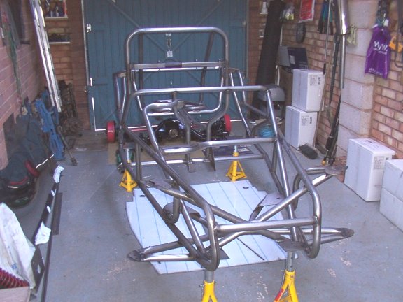
Well now the garage is fit to bursting, so first job is to try and sort out all the stuff we 'dumped' in the garage after getting back from collection day yesterday. I put the Recardo seats upstairs in the spare room, (with the bosses permission of course). The glass under the bed and then hung everything I could on the walls , (the garage walls that is !), then put the rest up in the storage space above my garage door. The 5 Alloy wheels seem to take up a lot of space, as does the carpet supplied by RHE. Now I seem to have enough room to work and the chassis is on axle stands waiting to be painted.
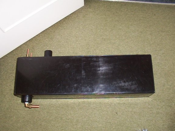
That's used up most of Sunday, so now it's off to watch the video's.. 15/12/01 Finally finished painting the chassis, it's amazing who long it takes to paint all the chassis tubes. The paint has covered well and the finish is very good, shame none of the tubes are seen once the 2B is completed, (apart from the Roll-Bar). My plastic petrol tank arrived today from Chris Gibbons . Very nice job and complete with baffle and bottom exit for my Injection system. I can thoroughly recommend Chris for his excellent work and it cost me £80 including postage and packaging.
I feel a lot more confident now after watching the video's, so I decided to fit the back axles assembly. I used the same technique as I the video and balanced the chassis on house bricks, (covered in cardboard, 3 bricks high), the chassis now rocks gently with the centre of balance such that the back end is heavy. I put a weight in the front to lift the backend then slid the axle assembly under the chassis. Although two people helped in the video I managed okay on my own. Once the axle assembly was lined up under the hole in the chassis mounting plate, I took the weight off the front and lowered the backend down onto the axle assembly. It was a bit of a pain 'guessing' where the two holes for the diff mount have to be drilled, I ended up with one of the holes elongated to get It to line up, but a nice big washer hides the hole. Everything basically went as the video, I used the big cup washer from the front suspension under the rubber mounting and the cup washer from the front roll bar. Rather than chisel out a large hole under the axle sub frame mount I drilled several larger holes enabling me to get a nut and washer up into the void in the subframe. I did not lean the chassis up against the wall on it's side as in the video, I managed to jack the whole lot up enough to get underneath.
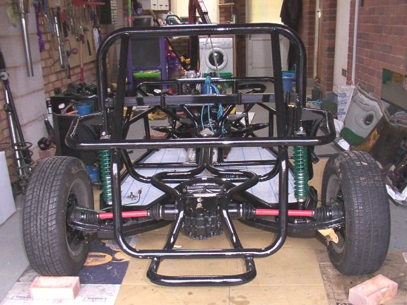
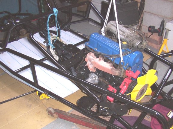
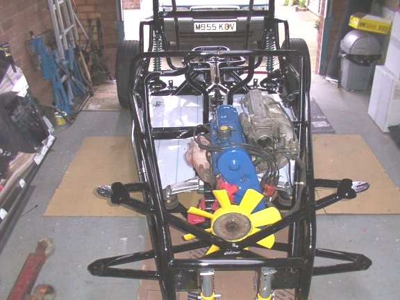
I bought the rear coil-over shocks from RHE, these were simple to fit, just a matter of cutting off enough of the roll bar bottoms to allow the back end to sit low enough. Apparently the bolts in the top and bottom coil-over shocks should be parallel with the half shafts when all the car is fully loaded. Mine sits a bit high at the moment as I did not want to cut off too much of the roll bar. Now it's starting to look better, we have rear suspension and wheels!. At the moment I am using the wheels and tyres from the donor , but will eventually fit my nice RHE alloy's. It was at this point that I decided to get some of the bits ready for the front sliding pillar suspension. The first strut from the donor came apart no problem, then disaster hit. Just as Richard say's in the video 'be careful as it is very easy to shear off the pinch bolt for the bottom swivel joint', mine sheared off, blast now I will have to try and drill out the bolt and replace it with a high tensile nut and bolt. After several attempts and two broken drills I decided to take the bottom swivel into work to see if they could drill it out for me. 16/12/01 Had another look at the rear suspension, mine is definitely sitting too high. I decided to take some more off the bottom of the roll bar tubes. I was amazed just how much I had to take off, almost as much as it is possible. The coil-over shocks were re-fitted and now the back end sits just right, with the drive shafts parallel with the top and bottom coil-over shock bolts when fully loaded. Assembled the engine/gearbox back together with a new clutch. Had another look at the video to see how RHE squeezed the engine in . RHE stress this is a difficult operation and requires two people. I had no problems on my own just gently lowering and moving forward just a little at a time. At about halfway I lifted up the gearbox end with a rope, then slid my trolley jack underneath the end of the gearbox. There was no need to grind off the gearbox web as instructed in the video or cut down the gearbox mounting plate on the chassis.
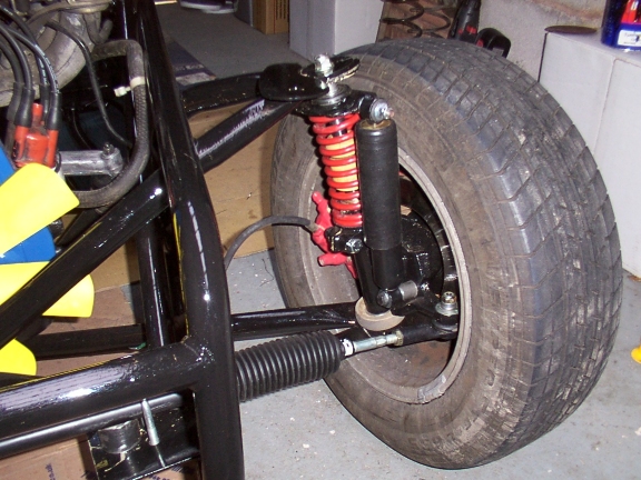
Basically no problems at all, engine went in fine, the EFI unit on the engine has to be lowered yet. I have elft the old exhaust manifold on at the moment Next weekend the bit I have not been looking forward to.. Assembly of the dreaded sliding pillar suspension. This weekend I decided to tackle the sliding pillar suspension and get a rolling chassis. I know people will say, 'why on earth did you go for the sliding pillar option and not buy the wishbone pack ?'. Well I decided to spend the money one alloy wheels, Recardo seats, etc as included in the £1835 kit. I also thought that as there had been so many problems with the S.P plenty of advice and solutions will be available. In any event if I am not happy with the S.P I could change at a later date by purchasing the wishbone add on kit from Sid's workshop, and have kept the original steering rack for that reason. Right first job was to cut up the sierra strut and get the chrome shaft out. No problems there, lot's of hot messy oil over the ground !. Good news both my chrome shafts have the correct 9mm nut/thread at the bottom. I filed off the sleeve rather than drill as tricky suggests. When offered up to the chassis the chrome shaft appears to fit okay but once the chrome shaft locator , (top hat to me and you), is slid on it does not sit flat on the bottom wishbone arm. There is a 2 mm gap at the front with the back edge of the top hat on the wishbone seat. I made up an angled spacer to sit under the top hat to compensate. The same for the other side. Right, now to assemble the swivel joint, blimey ! what a lot of bits to assemble correctly. One of my swivel joints has had the pinch bolt drilled out at work, (it sheared off !), so I also fitted a nice new nut/bolt in the other swivel. The chrome shaft was a very very tight fit in the bronze bushes, so as 'Tricky Dicky' says, I filed the bushes out with emery paper. The rest of the assembly went okay but as normal I had to grind down my spring compressors to get them out, they had to be 'thinned' out quite a lot. I also managed to lever apart the wishbones with a sprag of wood as Tricky say's to get a nice tight fit. I also drilled the chrome shaft locator and bolted them to the lower wishbone arm with 2BA screws.
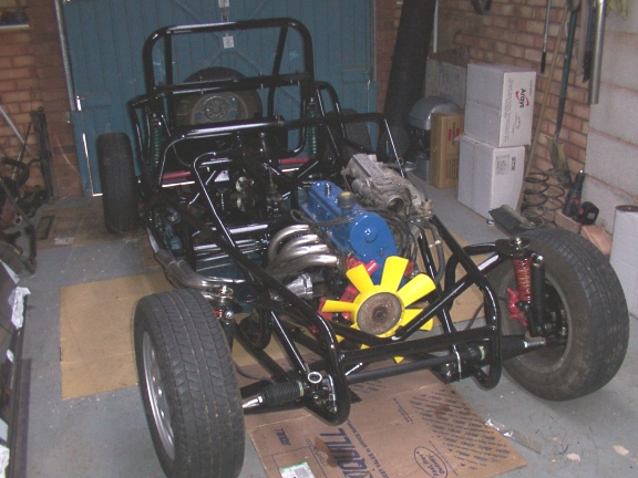
As expected I had the same problem as most people seem to have with the Spring/Wheel clearance, or lack of it. I am using the donor 195/65/14 and Ghia alloy wheels, I measured the RHE alloys and noticed the offset is better and will give me a bit of clearance, but to make sure I have ordered spacers and studs . I do however have plenty of clearance between the lower end of the chrome shaft, and the inside of the wheel rim, and will have even more with the 15" RHE alloys. Well now I have a rolling chassis, and can at least push it up and down the garage..
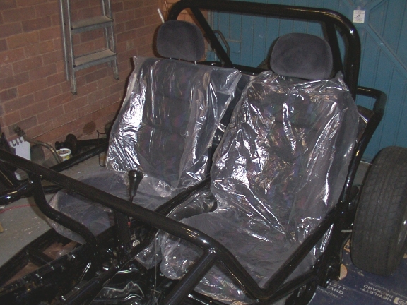
Now that I have a rolling chassis it would be a good idea if I could connect the wheels together, time to put the steering rack in. I followed the video but instead of using the spacers provided, (bits of flat steel), I engineered my own and will weld then to the chassis . I am having a bit of a problem getting the taper to bite, as the nyloc starts to tightens up before the taper has locked. I will get a normal nut , tighten that up then put the nyloc nut on after. I have had to use a spacer washer as the taper pulls through the fixing point a bit. Unlike Tricky suggests I have not 'waggled' a drill around in the top of the track rod end fixing hole, but fitted mine from the bottom as Mr Ford intended. At the moment I have guessed the camber by eye, and the toe-in. There does seem to be negative castor , so the steering self centre should be okay. If there is a problem with not enough negative camber or castor I will alter the slot in the top wishbone arm to suite. I know some people have filed out the slot another ½" to get enough negative camber. Steering rack in, looks like there is just enough room for the connecting rod to just miss the 4-into-one manifold. Next thing is to fit some interia panels and the steering wheel. So on to fitting the floor, the 3.3 high-nox drills seem to be just the job for drilling the stainless sheet, and the floor is finished in no time. I will pop rivet later. Had a nice Christmas and managed to stay away from the 2B until today, (went to the pictures yesterday to see Lord of The Rings, great film). Now was time to attempt my first bit of panel bending, the rear seat panel. I watched the video which mad it seem quite easy, so I then set aside a large area of cardboard on the garage floor. To my surprise the panel bent as expected, although the stainless does seem a bit harder to bend than the mild steel Richard uses in the video. The panel fitted quite well into the chassis with the bottom 'clipping' in behind the head of the floor/rear subframe bolts as in the video. At this point I decided to strip off the protective coating for the stainless, as it is a pain to get off once screwed/riveted together if you forget to peel back the fixing area, (as I seem to !). It doesn't matter if I scratch the interior panels anyway, as they will all be carpeted in time. There seem to be a lot of gaps, which will need filling to stop the water getting in. The tunnel sides were next, no problems here just simple 1" bends along the bottom of each panel and a couple of mouse holes cut into each side to allow for the chassis tubes and access to the Speedo cable. I am using No 8 ½ "pan head self tappers at the moment, with a view to replacing with pop rivets and 6mm bolts for the floor at a later date when I am sure everything fits as it should. It is surprising how much everything stiffens up when screwed together and seems quite strong. Even so I have also fitted additional floor strengthening across the bottom of the chassis at the point of the rear sub mounting plate, and about 15cm away from the chassis rube where the foot-well starts. I have used 40mm by 3mm angle , (1 ½" x 1/8" ), this also provides fixing points and support for the seats. The inside seat belt fixing points will also use this strengthening bar. Note:- a small tip, use gloves when panelling, I have numerous cuts on my hands/fingers and lots of blood stains on the stainless !. So time to put the seats in and see if they fit!. I have bought the Recardo seats from RHE, these are very nice fancy seats and are narrower than the sierra seats. However to my surprise I still had to remove stuff from the sides of the seats to get them in. There is a little forward and backward movement, but not the full travel. It must be a very tight fit for the sierra seats !. At least I did not have to take a hammer to my nice new Recardo seats as Richard does to the sierra ones in the video. I can use the height adjustment but will have to make up an extension for the operating arm.
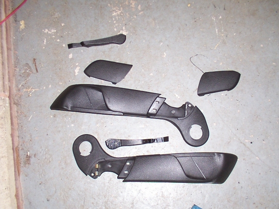
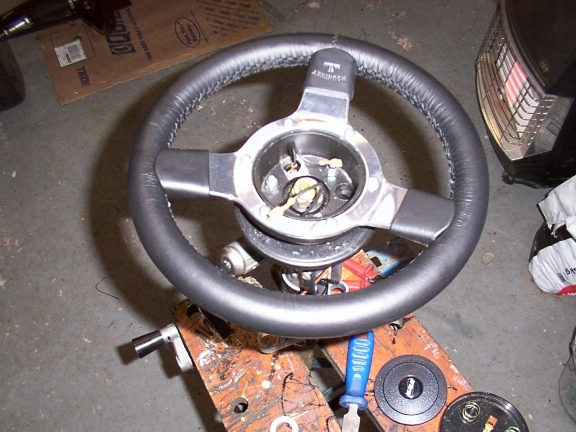
The seats are only provisionally in place and the tunnels sides are only held with self tappers at the moment, this means I can keep removing both items to get access to the inside of the tunnel for routing the wires, brakes pipes and fuel lines. My next job now that the seats are in position is to fit the steering wheel. I have bought the RHE supplied Mountney Wheel and decided to fit it before the SVA but covered with thick padding and hope it passes. The Mountney comes with very little instructions and it took me a while to figure out how it came apart, you just lever off the boss. I had been trying to undo the screws in the back. The sierra wheel came apart no problem and the Mountney went on without any fuss. Note, make sure you can find the ignition keys from the donor car, I had trouble getting the sierra boss off as the steering lock was on and I could not find the keys !.
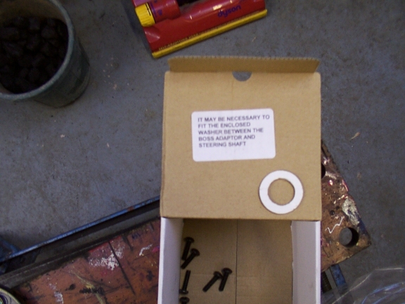
There is a note inside the Mountney boss kit which states you made need the enclosed washer, err I could not find any use for it or decide where it would go…answers on a postcard please..
|
![]()